The world of semiconductor design is rapidly evolving. As transistors shrink to atomic scales and the limitations of Moore’s Law become more apparent, the VLSI (Very Large-Scale Integration) industry is moving beyond traditional monolithic chips toward advanced packaging solutions such as chiplets and 3D ICs. These cutting-edge approaches are redefining physical design methodologies, enabling more powerful, efficient, and cost-effective systems. But what exactly are chiplets and 3D ICs — and how are they transforming the future of physical design? For decades, semiconductor innovation has been driven by Moore’s Law, which predicts that the number of transistors on a chip doubles roughly every two years. However, as we approach the physical limits of silicon scaling (below 3nm), continuing to pack more transistors onto a single die has become economically and technically challenging. That’s where heterogeneous integration, chiplets, and 3D ICs come in — representing a new era in semiconductor design that focuses on system-level performance rather than transistor count alone. A chiplet is a smaller, functional block or die that performs a specific task — such as CPU, GPU, or memory processing — integrated together on a single package to form a complete system. Lower manufacturing cost Better yield rates Design reusability Faster time-to-market Examples include: AMD’s Ryzen and EPYC processors built with multiple chiplets for cores and I/O. Intel’s Foveros and EMIB technologies enabling heterogeneous integration. 3D Integrated Circuits (3D ICs) take integration to another level — literally. Here, multiple dies are stacked vertically using Through-Silicon Vias (TSVs) or micro-bumps, allowing shorter interconnect paths and higher data bandwidth between layers. This vertical stacking enables: High performance and low latency Smaller form factor Lower power consumption Better functionality per unit area The introduction of chiplets and 3D ICs has revolutionized the physical design flow. Traditional flat design methodologies no longer apply — engineers must now consider multi-die, multi-layer, and thermal-aware design challenges. Here’s how these technologies are reshaping every aspect of physical design: In traditional design, floorplanning focuses on a single die layout. In chiplet and 3D IC design, system-level floorplanning determines: Placement of each die or chiplet Inter-die connectivity Power and thermal distribution Signal and clock integrity EDA tools such as Cadence Integrity 3D-IC and Synopsys 3DIC Compiler are now enabling multi-die co-design and optimization. In a chiplet ecosystem, data transfer between dies is crucial. Engineers must define: High-speed interconnect standards (like UCIe, AIB, or BoW) Die-to-die routing optimization Partitioning logic between dies based on functionality, latency, and power needs This adds a new dimension to placement, routing, and verification strategies. Stacking dies in 3D structures increases thermal density, making heat dissipation one of the biggest challenges. Designers now use thermal-aware placement and advanced cooling solutions (liquidcooling, microchannels) to prevent hotspots. Power delivery networks (PDNs) must also be redesigned to manage vertical power flow and reduce IR drop. As interconnect paths shorten and layer-to-layer communication increases, signal integrity, crosstalk, and timing closure become more complex. Verification for 3D ICs and chiplets is far more challenging than for traditional SoCs. 3D DRC (Design Rule Check) Layout vs. Schematic (LVS) checks across dies Thermal and mechanical stress analysis Power intent verification EDA vendors are actively integrating AI and automation to manage this verification complexity. These benefits make chiplets and 3D ICs vital for future applications such as: AI accelerators and HPC chips 5G baseband processors Autonomous vehicle SoCs Edge computing systems EDA companies are leading the transition toward multi-die design. Some key innovations include: These tools integrate AI-based optimization, cloud scalability, and cross-domain simulation to make 3D design workflows more efficient and collaborative. Despite their advantages, engineers face several hurdles in adopting these technologies: AI is becoming a game-changer in multi-die physical design optimization. Predict thermal hotspots and optimize placement. Automate die partitioning based on power and performance metrics. Perform fast PPA (Power, Performance, Area) trade-off analysis. Accelerate timing closure and routing convergence. With the emergence of AI-driven design tools like Synopsys DSO.ai and Cadence Cerebrus, design teams can drastically shorten development cycles and improve design quality. The next generation of physical design engineers will operate in a world of heterogeneous integration, AI-assisted automation, and cloud-based EDA environments. Standardized chiplet ecosystems for plug-and-play design. Automated 3D design space exploration using AI. Sustainability-focused layouts to reduce power and waste. Open-source 3D design education platforms for academic use. In essence, physical design is evolving from a 2D layout problem to a multi-dimensional system-level challenge — demanding new tools, skills, and collaboration. For students and professionals in VLSI, this transformation means learning beyond traditional EDA workflows. Key steps to prepare include: Understanding 3D integration principles and chiplet architectures. Gaining hands-on experience with EDA tools supporting 3D and chiplet flows. Developing skills in AI, scripting (TCL/Python), and cloud design environments. Exploring open-source projects like Open3DFlow or TinyTapeout to understand packaging-level design. By embracing these skills early, engineers can position themselves at the forefront of the semiconductor design revolution. Chiplets and 3D ICs mark a fundamental shift in how chips are designed, assembled, and optimized.1. The Shift Beyond Moore’s Law
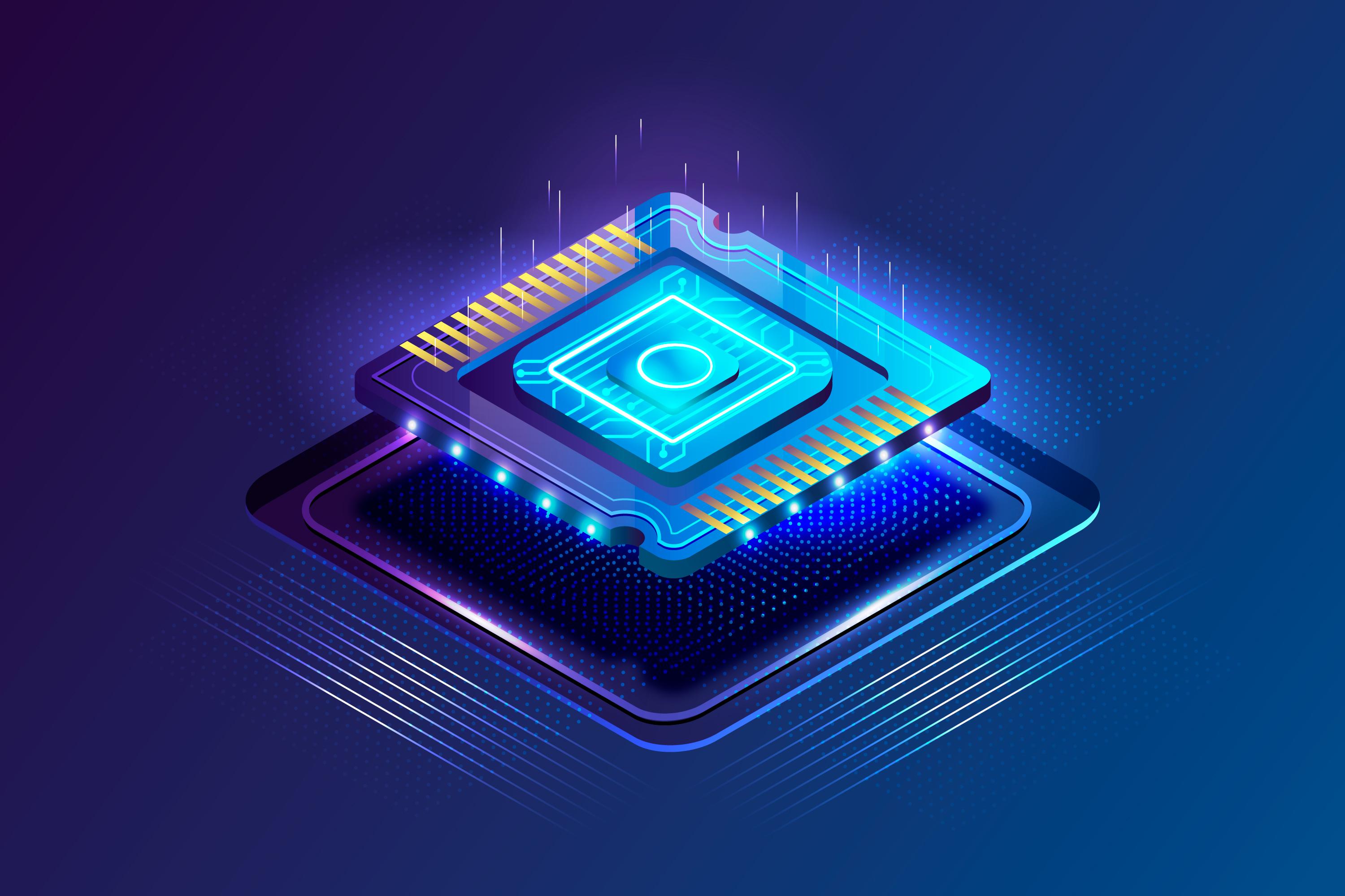
2. Understanding Chiplets and 3D ICs
Chiplets: The Modular Approach to Design
Instead of building one large, complex monolithic die, designers can assemble multiple chiplets like Lego blocks, offering:3D ICs: The Vertical Revolution
3. How Chiplets and 3D ICs Are Transforming Physical Design
a. Floorplanning Becomes System-Level
b. Interconnect Planning and Die Partitioning
c. Thermal and Power Management
d. Signal Integrity and Timing Closure
EDA tools must handle multi-die timing analysis, ensuring that all layers operate synchronously without introducing delay or skew.e. Verification Complexity
Physical verification now includes:4. Advantages of Chiplets and 3D ICs in Modern Design
5. The Role of EDA Tools in 3D IC and Chiplet-Based Design
Synopsys 3DIC Compiler: Offers unified design, analysis, and verification for multi-die systems.
Cadence Integrity 3D-IC Platform: Enables full system co-design from packaging to silicon.
Mentor Xpedition Substrate Integrator (SI): Facilitates planning for advanced packaging.
OpenROAD / Open3DFlow: Open-source initiatives bringing 3D IC design education to universities.
6. Challenges in Physical Design for Chiplets and 3D ICs
Thermal management — Stacked dies increase power density.
Testing and yield — Testing stacked dies individually and together is complex.
Design ecosystem fragmentation — Lack of universal standards for chiplet interfaces.
EDA limitations — Traditional tools are not fully optimized for 3D partitioning.
Supply chain and packaging constraints — Advanced packaging requires high-precision manufacturing
Addressing these challenges requires close collaboration between EDA vendors, foundries (like TSMC, Intel, Samsung), and design houses.7. How AI and Machine Learning Are Enhancing Chiplet and 3D IC Design
Machine learning algorithms help:8. The Future of Physical Design: A Multi-Dimensional Evolution
Some key future trends include:9. Preparing for the New Era of Physical Design
Conclusion
As monolithic scaling reaches its limits, the future of physical design will depend on integration, innovation, and intelligence — connecting multiple dies, layers, and technologies into a single, high-performance system.
How to Choose Your First RTL Design Project
Learn how to choose your first RTL design project with practical tips, beginner-friendly project ideas, Verilog best practices, and guidance to build a strong VLSI portfolio.
Turning VLSI Learning into a Career Opportunity – Step by Step
Learn how to turn your VLSI learning into a successful semiconductor career with a step-by-step roadmap covering skills, projects, interview preparation, and industry expectations.
What to Focus on First When Entering the VLSI Domain
Discover what to focus on first when starting a VLSI career. Learn the essential concepts, skills, projects, and learning roadmap needed to become industry-ready in the semiconductor domain.
Creating a Personal Learning Strategy for VLSI Success
Learn how to create a personalized VLSI learning strategy with practical milestones, project planning, skill assessment, and industry-focused guidance to become job-ready faster.
How to Track Your Progress While Learning VLSI
Learn how to track your progress while learning VLSI with practical milestones, project-based assessments, interview readiness tips, and proven strategies to become industry-ready.
.


Hours
2-98/1, Gurram Guda Road, Gurram Guda, Hyderabad, Rangareddy, Telangana, 501510
Copyright 2025 © VLSI Technologies Private Limited
Designed and developed by KandraDigitalCopyright 2025 © VLSI Technologies Private Limited
Designed, Developed & Marketing by KandraDigital