If you are learning Verilog or SystemVerilog for the first time, two terms appear almost immediately: simulation and synthesis.
Both are essential parts of the VLSI design flow, but they perform completely different jobs. This is where many beginners get confused.
A student may write Verilog RTL, run it successfully in a simulator, observe the expected waveform, and conclude that the design is ready for hardware. But successful Verilog simulation does not automatically mean that the RTL will synthesize into the intended hardware.
Similarly, synthesis does not replace simulation. A synthesis tool transforms RTL into a hardware-oriented representation, but functional verification still requires simulation, formal methods, or other verification techniques.
Understanding the difference between simulation vs synthesis is therefore one of the first important steps toward thinking like an RTL design engineer.
What Is RTL Simulation?
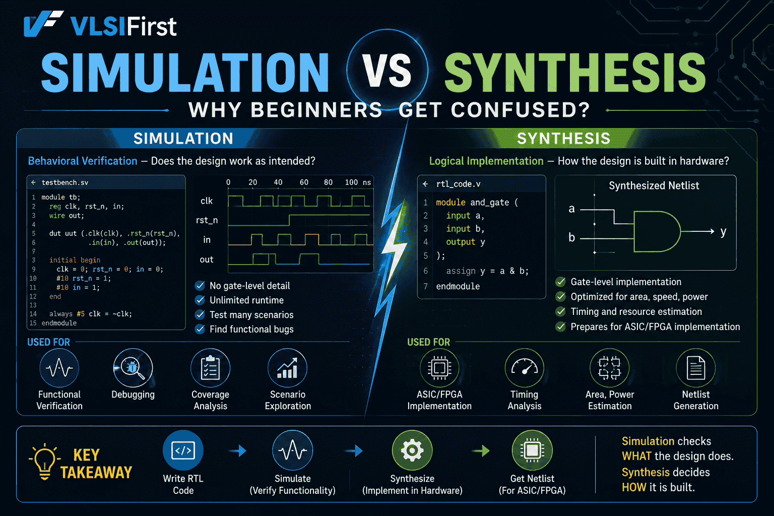
RTL simulation is the process of executing your Verilog or SystemVerilog RTL in a simulator to observe how the design behaves over simulation time.
The simulator applies inputs, evaluates the RTL, and produces outputs and signal activity. Engineers can then inspect waveforms, assertions, logs, and testbench results to determine whether the design behaves according to its specification.
AMD describes RTL behavioral simulation as a way to verify RTL before translation by synthesis or implementation tools, primarily checking whether the code functions as intended.
For example, suppose you write a four-bit counter:
always @(posedge clk) begin
if (rst)
count <= 4'b0000;
else if (enable)
count <= count + 1'b1;
end
During simulation, you can observe:
- Clock transitions
- Reset behavior
- Enable behavior
- Counter values
- Output transitions
- Unexpected X values
- Timing relationships
This is functional verification at the RTL level.
What Is RTL Synthesis?
RTL synthesis is different.
Synthesis converts your RTL description into a gate-level netlist or another implementation-oriented representation that can ultimately be mapped onto hardware.
A simplified flow is:
Specification → RTL → Simulation/Verification → Synthesis → Gate-Level Netlist → Implementation
Synopsys describes RTL synthesis as the stage where a verified HDL representation is converted into a gate-level netlist that can feed subsequent physical implementation stages.
The synthesis tool analyzes your RTL and determines what hardware is required.
For example, your counter RTL may result in hardware containing:
- Flip-flops
- Adders
- Multiplexing logic
- Reset circuitry
- Clock connections
The RTL is therefore a description of hardware behavior, while synthesis determines an implementation of that behavior using available technology resources.
Simulation vs Synthesis: The Basic Difference
The easiest way to remember the distinction is:
Simulation | Synthesis |
Checks behavior | Creates hardware representation |
Uses a simulator | Uses a synthesis tool |
Executes the RTL model | Transforms RTL |
Produces waveforms/logs | Produces a gate-level netlist |
Mainly used for functional verification | Used for hardware implementation preparation |
Works with testbench stimulus | Uses RTL, constraints and libraries |
Helps find functional bugs | Helps analyze implementation characteristics |
Does not itself create hardware | Produces hardware-oriented logic representation |
So when someone asks "Does my Verilog code work?", simulation helps answer that question.
When the question becomes "What hardware will this Verilog code produce?", synthesis becomes important.
Why Beginners Confuse Simulation and Synthesis
The confusion usually starts because both processes work with the same RTL source code.
You may write:
design.v
testbench.v
Then use an EDA tool to simulate the design.
Later, you may use another tool or another stage of the same design environment to synthesize design.v.
Because the same RTL appears in both workflows, beginners often assume that simulation and synthesis are essentially the same operation.
They are not.
The simulator asks:
"Given these inputs and simulation rules, what does this RTL model do?"
The synthesis tool asks:
"What hardware structure can implement this RTL behavior?"
That distinction is fundamental to understanding the RTL design flow.
Simulation Does Not Create Physical Hardware
This is one of the most important concepts for beginners.
When you simulate:
assign y = a & b;
the simulator evaluates the expression and shows the resulting value of y.
It does not physically create an AND gate.
During synthesis, however, the tool can infer that the required hardware behavior corresponds to an AND function and represent it in the resulting hardware structure.
This is why simulation and synthesis in VLSI serve different purposes.
What Happens During RTL Simulation?
A simplified Verilog simulation flow looks like this:
Step 1: Compile the HDL
The simulator reads Verilog or SystemVerilog source files.
Step 2: Elaborate the Design
The tool builds the design hierarchy, resolves module instances and parameters, and prepares the simulation model.
Step 3: Start the Testbench
The testbench generates inputs for the DUT, or Design Under Test.
Step 4: Execute the RTL
The simulator evaluates events according to HDL simulation semantics.
Step 5: Record Results
You can inspect:
- Output values
- Internal signals
- Waveforms
- Assertions
- Simulation logs
This is why students should learn how to read waveforms alongside Verilog coding.
What Happens During RTL Synthesis?
The synthesis process takes a different path.
A simplified flow is:
RTL Code
↓
Elaboration
↓
RTL Analysis
↓
Logic Optimization
↓
Technology Mapping
↓
Gate-Level Netlist
The synthesis tool interprets synthesizable RTL and maps the required logic into cells or resources available in the target technology.
Depending on the target, this may involve standard-cell libraries for ASICs or FPGA-specific resources for FPGA designs.
Synthesis can also perform optimization based on constraints and tool settings.
Modern synthesis flows therefore involve much more than simply "converting Verilog into gates."
Why Does Synthesizable Verilog Matter?
This is where many beginners encounter their first major surprise.
Not every Verilog construct is intended to become physical hardware.
For example, a testbench may contain:
#10 data = 1;
The delay is useful for simulation, but a synthesis tool generally cannot interpret #10 as a physical hardware component.
Similarly, constructs used only for testbench activity, debugging, or simulation control may not be synthesizable.
Therefore, learning synthesizable Verilog is essential for RTL designers.
VLSIFirst's RTL curriculum explicitly covers synthesizable versus non-synthesizable constructs, along with simulation, synthesis, event scheduling and race conditions.
A Simple Example of Simulation vs Synthesis
Consider:
always @(posedge clk) begin
q <= d;
end
During simulation, you might see:
Clock ↑ ↑ ↑ ↑
D 1 0 1
Q 1 0 1
The simulator shows the behavior of q over time.
During synthesis, the tool recognizes the RTL behavior as a storage element and can infer a flip-flop.
So:
Simulation:
"What happens to q when the clock changes?"
Synthesis:
"What hardware is required to make q behave this way?"
This distinction becomes much clearer when students learn to think about RTL as a hardware description, rather than as ordinary software code.
Can RTL Simulate Correctly but Synthesize Differently?
Yes.
This is one of the most important reasons beginners need to understand simulation-synthesis mismatch.
Certain coding practices can produce behavior in simulation that does not correspond to the intended synthesized hardware.
Potential causes include:
- Non-synthesizable constructs
- Incomplete combinational assignments
- Incorrect sensitivity behavior in older Verilog coding styles
- Race conditions
- Improper blocking/nonblocking usage
- Ambiguous reset behavior
- Multiple drivers
- Tool-specific interpretation
- Unsupported language constructs
Cadence specifically identifies simulation/synthesis mismatch as an RTL quality concern that linting can detect, including unsynthesizable constructs and issues that can create pre- and post-synthesis behavioral differences.
This is why good RTL engineers do not write code with the attitude:
"It simulates, so it must be correct."
Instead, they ask:
"Does it simulate correctly, synthesize as intended, and satisfy the implementation requirements?"
Pre-Synthesis and Post-Synthesis Simulation
Beginners often assume there is only one type of simulation.
In practice, simulation can happen at different stages.
Pre-Synthesis RTL Simulation
- This is performed using the original RTL.
- Its main purpose is to verify functional behavior before synthesis.
- It is generally faster and easier to debug.
Post-Synthesis Simulation
- After synthesis, the generated gate-level representation can also be simulated.
- This allows engineers to check whether the synthesized implementation behaves as expected.
- AMD documentation describes post-synthesis simulation as a way to simulate a synthesized netlist and verify that the resulting design still meets functional requirements.
For beginners, the important concept is:
RTL simulation checks the design before synthesis; post-synthesis simulation checks the synthesized representation.
Why Synthesis Results Matter Beyond Functionality
Suppose two RTL implementations produce the same output during simulation.
They may still produce different hardware characteristics after synthesis.
One implementation could require:
- More logic
- More area
- Longer critical paths
- More power
- Different resource utilization
This is why synthesis optimization is important.
RTL engineers increasingly need awareness of area and power optimization, timing, resource utilization and implementation constraints.
Synopsys notes that modern RTL development increasingly benefits from early PPA—power, performance and area—feedback rather than treating these considerations purely as a later-stage concern.
Simulation Tools vs Synthesis Tools
Students also frequently confuse simulation tools with synthesis tools.
Simulation tools include environments such as:
- ModelSim/Questa
- VCS
- Vivado Simulator
- Xcelium
- Verilator
Synthesis tools include tools such as:
- Synopsys Design Compiler
- Cadence Genus
- Vivado synthesis
- Quartus synthesis
Some EDA platforms provide both capabilities in the same overall environment, which can make the distinction less obvious.
VLSIFirst's guide to RTL design tools covers simulation, modeling and synthesis tools and emphasizes that students should understand the complete workflow rather than treating simulation as the entire RTL process.
Where Does Verification Fit?
Verification is not something that happens only after synthesis.
In a typical front-end workflow, engineers verify the RTL before committing it to later implementation stages.
A simplified process is:
Specification
↓
RTL Design
↓
RTL Simulation + Verification
↓
Synthesis
↓
Gate-Level Analysis/Verification
↓
Physical Implementation
RTL simulation therefore forms an important part of digital design verification.
VLSIFirst's RTL Design and Verification course describes the broader flow from RTL through synthesis and verification, including practical exposure to design tools.
How Beginners Should Learn Simulation and Synthesis
Do not try to learn both concepts by memorizing definitions.
Use a small project.
For example, build a counter.
Stage 1: Write RTL
Create the counter using synthesizable RTL.
Stage 2: Create a Testbench
Generate:
- Clock
- Reset
- Enable
Stage 3: Run RTL Simulation
Check the waveform.
Does the counter reset correctly?
Does it increment on the expected clock edge?
Stage 4: Synthesize It
Run the synthesis tool.
Examine:
- Inferred hardware
- Resource utilization
- Logic structure
- Timing information
Stage 5: Compare Your Understanding
Ask:
What did I write?
What did simulation show?
What hardware did synthesis infer?
That exercise teaches the relationship between RTL code, Verilog simulation, synthesis and actual hardware far better than memorizing definitions.
For more project-based practice:
Student Friendly RTL Projects for Academic Practice
Common Beginner Mistakes
Mistake 1: Thinking Simulation Equals Hardware
A waveform is a simulation result, not a physical chip.
Mistake 2: Assuming Every Verilog Statement Synthesizes
Verilog is a hardware description language, but not every language construct is suitable for synthesis.
Mistake 3: Ignoring Synthesis Reports
A functionally correct RTL design can still have poor area or timing characteristics.
Mistake 4: Debugging Only Through Simulation
Simulation is essential, but synthesis and implementation feedback are also important.
Mistake 5: Ignoring Coding Style
Poor RTL coding practices can cause simulation-synthesis mismatches and unintended hardware.
VLSIFirst's discussion of common RTL mistakes highlights issues such as unintended latches, incorrect assignment usage, non-synthesizable constructs and insufficient attention to synthesis constraints.
A Simple Way to Remember the Difference
If you are preparing for a VLSI interview, remember this:
Simulation asks:
"Does my RTL behave correctly for the given stimulus?"
Synthesis asks:
"What hardware can implement my RTL, and what does that implementation look like?"
And the complete engineering question is:
"Does the RTL behave correctly, synthesize into the intended hardware, and meet implementation requirements?"
That is the mindset you should develop as an aspiring RTL engineer.
Final Thoughts
Understanding simulation vs synthesis is one of the most important foundations for students entering RTL design and VLSI.
Simulation allows you to observe and verify the behavior of your RTL. Synthesis transforms synthesizable RTL into a gate-level representation that can be used for subsequent hardware implementation. They are connected stages of the same design flow, but they answer different questions.
The most important lesson is that a successful simulation is necessary but not sufficient.
As you progress, learn to connect three things:
RTL Code → Simulation Behavior → Synthesized Hardware
Once you understand this relationship, concepts such as synthesizable Verilog, gate-level netlists, synthesis optimization, timing analysis, and simulation-synthesis mismatch become much easier to understand.
For students, the best approach is practical: write small RTL modules, simulate them, inspect the waveforms, synthesize the same designs, study the resulting reports, and compare your expectations with what the tools actually produce.
That is how simulation and synthesis stop being two confusing terms and become two essential parts of the RTL design flow.