
Learning Verilog is an exciting milestone for anyone aspiring to build a career in VLSI. It is the language that allows engineers to describe digital hardware, implement complex circuits, and transform logical ideas into synthesizable designs. However, every beginner encounters challenges while writing their first few Verilog programs. Compilation errors, simulation mismatches, unexpected outputs, and confusing waveforms are all part of the learning process.
The good news is that these mistakes are not signs of failure; they are opportunities to build stronger engineering skills. In fact, many of the errors beginners make today are the same ones experienced RTL engineers learned to overcome early in their careers.
Understanding these common mistakes before they become habits can significantly improve your coding quality, reduce debugging time, and prepare you for industry-level RTL design. This article discusses the most frequent Verilog mistakes beginners make, why they occur, and practical ways to avoid them.
Why Beginners Make Verilog Mistakes
Unlike conventional programming languages, Verilog describes hardware behavior. This means your code represents physical digital circuits rather than sequential software instructions. Many students approach Verilog with a software programming mindset, leading to misunderstandings about timing, concurrency, registers, and combinational logic.
Learning Verilog successfully requires:
- Understanding digital electronics.
- Thinking in terms of hardware implementation.
- Practicing simulation and verification.
- Developing structured debugging habits.
Once this mindset develops, writing reliable RTL becomes much easier.
Mistake 1: Writing Code Without Understanding the Circuit
Many beginners begin coding immediately after reading a problem statement.
Instead, start by answering:
- What should the circuit do?
- Is it combinational or sequential?
- What are the inputs?
- What are the outputs?
- How should signals change over time?
Drawing a simple logic or block diagram before coding helps prevent unnecessary errors.
Mistake 2: Confusing Blocking and Non-Blocking Assignments
One of the most common Verilog mistakes involves incorrect use of assignment operators.
Using the wrong assignment type can result in:
- Incorrect sequential behavior.
- Race conditions.
- Unexpected simulation results.
- Difficult-to-debug logic.
A good practice is to understand the purpose of each assignment type and use them consistently according to RTL coding guidelines.
Mastering this concept early saves countless debugging hours later.
Mistake 3: Ignoring Reset Logic
Reset functionality is essential in digital systems.
Beginners often:
- Forget to initialize registers.
- Leave FSMs without defined reset states.
- Ignore output reset conditions.
Without proper reset implementation, simulations may begin with unknown values, making debugging much more difficult.
Always verify reset behavior before testing functional logic.
Mistake 4: Ignoring Compiler Warnings
Many students stop reviewing messages once the compiler reports "Compilation Successful."
However, warnings often reveal:
- Width mismatches.
- Multiple drivers.
- Unused signals.
- Inferred latches.
- Unconnected ports.
Professional engineers treat warnings seriously because they frequently indicate underlying design issues.
Mistake 5: Writing Everything in One Module
Large monolithic modules quickly become difficult to understand.
Instead, divide your project into smaller functional blocks.
Examples include:
- Controller
- Datapath
- Counter
- Decoder
- Register File
Smaller modules improve readability, verification, debugging, and code reuse.
Mistake 6: Poor Signal Naming
Names such as:
- temp
- data1
- x
- abc
make RTL difficult to understand.
Use descriptive names like:
- clk_enable
- read_pointer
- write_pointer
- packet_valid
- data_ready
Good naming conventions improve collaboration and simplify debugging.
Mistake 7: Forgetting Default Conditions
Incomplete conditional logic may result in unintended hardware behavior.
Review your:
- If-else statements
- Case statements
- State transitions
Ensure every possible condition is handled appropriately.
Mistake 8: Weak Testbench Design
Many beginners spend hours writing RTL but only minutes creating a testbench.
An effective testbench should verify:
- Reset
- Normal operation
- Boundary conditions
- Invalid inputs
- Multiple operating scenarios
Without proper verification, hidden bugs often remain undiscovered.
Mistake 9: Not Using Waveforms Properly
Waveforms provide a visual representation of hardware behavior.
Instead of checking only the output signal, examine:
- Clock
- Reset
- Internal registers
- State transitions
- Counters
- Control signals
Careful waveform analysis often identifies problems much faster than repeatedly editing code.
Mistake 10: Copying Code Without Understanding It
The internet offers countless Verilog examples.
While these resources are useful for learning, blindly copying RTL creates problems during interviews.
Recruiters frequently ask:
- Why did you implement the logic this way?
- Explain the FSM.
- Describe signal flow.
- Why was this register necessary?
Understanding your own code is far more valuable than presenting a complicated project you cannot explain.
Mistake 11: Ignoring Corner Cases
Testing only the expected operating conditions leaves many issues undiscovered.
Always verify:
- Maximum values.
- Minimum values.
- Consecutive resets.
- Simultaneous control signals.
- Invalid inputs.
Industry verification emphasizes thorough testing rather than just demonstrating functionality.
Mistake 12: Poor Documentation
Documentation is often neglected until the project is complete.
Instead, record:
- Architecture decisions.
- Signal descriptions.
- Verification methodology.
- Debugging observations.
- Lessons learned.
Good documentation improves project quality and interview discussions.
Mistake 13: Skipping Manual Code Reviews
Simulation is not the only way to identify bugs.
Before running the design:
Read the RTL carefully.
Ask yourself:
- Does this logic match the specification?
- Are signals initialized?
- Are all conditions covered?
- Can another engineer understand this module?
Manual reviews frequently uncover mistakes before simulation begins.
Mistake 14: Not Practicing Incrementally
Some learners attempt highly complex projects immediately.
A better approach is gradual progression.
Start with:
- Multiplexer
- Decoder
- Counter
- Shift Register
Then move toward:
- FIFO
- UART
- SPI
- Memory Controller
- Protocol implementations
Incremental learning builds confidence while reinforcing fundamentals.
Mistake 15: Treating Debugging as Failure
Many beginners become discouraged when simulations fail.
In reality, debugging is a normal part of semiconductor development.
Every bug teaches:
- Better coding practices.
- Stronger analytical thinking.
- Improved verification skills.
- Greater understanding of hardware behavior.
Professional engineers spend significant time debugging because complex systems naturally require careful refinement.
Develop Habits That Prevent Mistakes
Instead of memorizing syntax alone, develop engineering habits.
Before completing any RTL module, verify:
- Functional requirements.
- Signal naming.
- Reset behavior.
- Module interfaces.
- Testbench coverage.
- Documentation.
- Simulation results.
Consistently following a checklist greatly improves code quality.
Practice with Real Projects
Nothing replaces hands-on implementation.
Projects such as:
- UART
- FIFO
- SPI
- ALU
- Traffic Light Controller
- Sequence Detector
- Memory Controller
introduce new debugging situations and reinforce best coding practices.
Learn Industry Coding Practices Through Practical Training
Avoiding common Verilog mistakes becomes easier when you receive guidance from experienced engineers and work on structured industry-style projects. Practical training exposes learners to coding standards, design reviews, simulation methodologies, verification planning, and debugging techniques that are routinely followed in semiconductor companies.
VLSIFirst offers hands-on learning through programs such as Semiconductor Fundamentals, Digital Electronics for VLSI, RTL Design and Verification, SystemVerilog & UVM, FPGA Design, ASIC Design, Physical Design, Static Timing Analysis (STA), Design for Test (DFT), Custom Layout Design, Low Power VLSI Design, and the Full Chip Design Program. These courses help students develop practical RTL design skills through real projects, structured assignments, comprehensive verification, and professional documentation aligned with industry expectations.
Final Thoughts
Every successful RTL engineer has made mistakes while learning Verilog. The difference lies in how those mistakes are handled. Beginners who analyze their errors, understand the underlying concepts, and continuously refine their coding practices progress much faster than those who rely solely on trial and error.
Rather than aiming for bug-free code from the beginning, focus on writing clean, modular, and understandable RTL. Verify your designs thoroughly, review your code systematically, document your learning, and treat every debugging session as an opportunity to improve.
With consistent practice and the right learning approach, today's beginner mistakes become tomorrow's valuable engineering experience. Mastering these fundamentals not only strengthens your Verilog skills but also prepares you for the expectations of professional RTL Design and Functional Verification roles in the semiconductor industry.
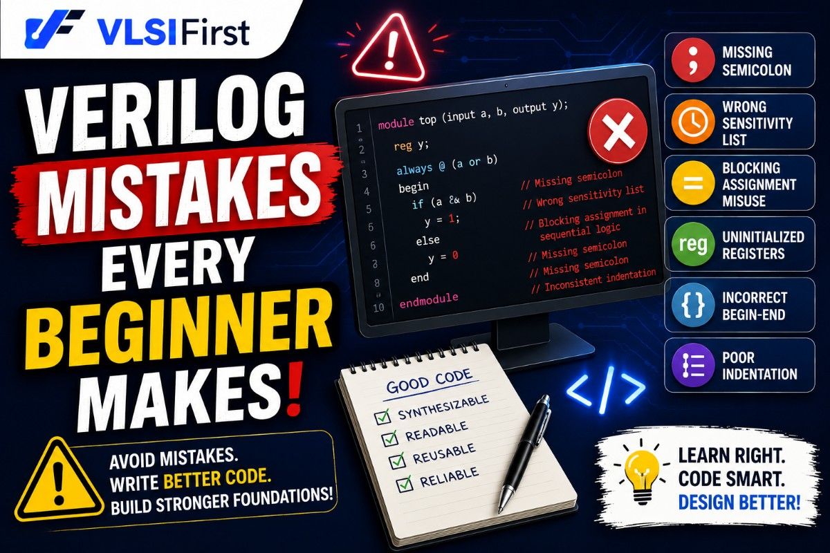
Verilog Mistakes Every Beginner Makes (and How to Avoid Them)
Discover the most common Verilog mistakes beginners make and learn practical tips to improve RTL coding, debugging, simulation, verification, and interview readiness.

Capstone Project Ideas for VLSI Students
Learn how to write a professional VLSI project report with the right structure, RTL documentation, verification strategy, debugging details, and interview-ready presentation tips.

What Makes a Good VLSI Project Report? A Complete Guide for Students and Freshers
Learn how to write a professional VLSI project report with the right structure, RTL documentation, verification strategy, debugging details, and interview-ready presentation tips.
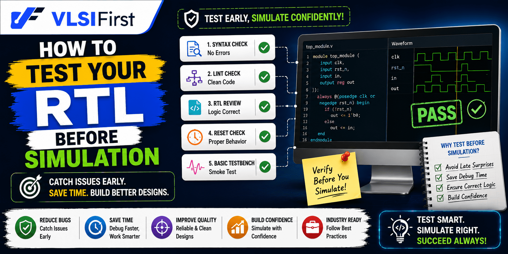
How to Test Your RTL Before Simulation: A Practical Pre-Simulation Checklist for Beginners
Learn how to test your RTL before simulation with a practical pre-simulation checklist. Improve Verilog quality, reduce debugging time, and build industry-ready RTL skills.

From Logic Diagram to Verilog Code – Complete Workflow
Learn the complete workflow from logic diagram to Verilog code, including specifications, RTL architec ture, coding, simulation, debugging, verification, and documentation.


Hours
2-98/1, Gurram Guda Road, Gurram Guda, Hyderabad, Rangareddy, Telangana, 501510
Copyright 2025 © VLSI Technologies Private Limited
Designed and developed by KandraDigitalCopyright 2025 © VLSI Technologies Private Limited
Designed, Developed & Marketing by KandraDigital